英语原文共 5 页,剩余内容已隐藏,支付完成后下载完整资料
外文翻译:
Simplified Design of Coupled Shear Wall
Systems for Typical Building Configuration
Abstract: For many years, coupled shear wall systems have been used as an effective way of controlling lateral stability for high rise
buildings. Shear walls have a large lateral stiffness compared to frame systems, and hence, they are often used where control of lateral
displacement is imperative. General design objectives for coupled shear walls were summarized from the available literature. Four different
configurations of coupling beams with aspect ratios of 2–4 were evaluated using SAP2000 software to obtain an approximate empirical
relationship to estimate the degree of coupling of a coupled wall system for a typical four-story hotel-type structure. The proposed equation
provides an accurate estimation of the degree of coupling. Using this empirical relationship, a simple procedure to incorporate coupling action
into the instantaneous design of shear walls was outlined. DOI: 10.1061/(ASCE)SC.1943-5576.0000700. copy; 2022 American Society of Civil
Engineers.
Introduction
A coupled shear wall can greatly improve the performance of individual shear walls. Designers have several options to provide coupling between shear walls. Proper design of coupled shear walls is not a simple task and if misused, coupled shear walls can compromise the overall integrity of the structure (deterioration of main wallcore and/or foundation uplift).
In the United States and many other locations in the world,common hotel-type structures are built on a regular basis. These buildings are usually 4–6 stories high and have shear walls as a lateral load resisting system. It is not uncommon for these shear walls to be connected by coupling beams spanning across hallways or over elevator entries. The main objective of this research is to provide the reader with a simple design (and design procedure) to be used when incorporating coupling beams into the lateral load resisting system.
Types of Coupling Beams
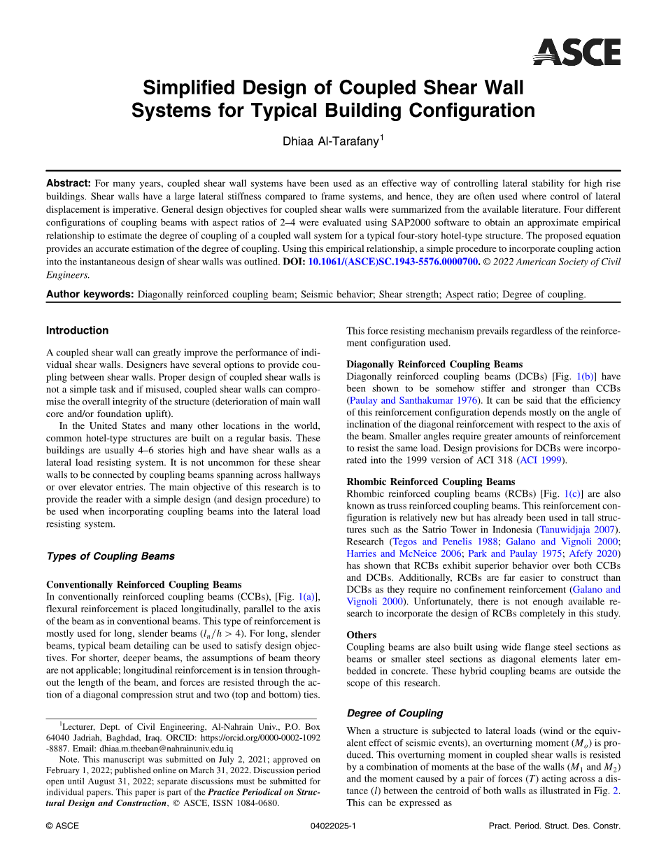
Conventionally Reinforced Coupling Beams In conventionally reinforced coupling beams (CCBs), [Fig. 1(a)],flexural reinforcement is placed longitudinally, parallel to the axis of the beam as in conventional beams. This type of reinforcement is mostly used for long, slender beams (ln=h gt; 4). For long, slender beams, typical beam detailing can be used to satisfy design objectives. For shorter, deeper beams, the assumptions of beam theory are not applicable; longitudinal reinforcement is in tension throughout the length of the beam, and forces are resisted through the action of a diagonal compression strut and two (top and bottom) ties.
Diagonally Reinforced Coupling Beams
Diagonally reinforced coupling beams (DCBs) [Fig. 1(b)] have been shown to be somehow stiffer and stronger than CCBs(Paulay and Santhakumar 1976). It can be said that the efficiency of this reinforcement configuration depends mostly on the angle of inclination of the diagonal reinforcement with respect to the axis of the beam. Smaller angles require greater amounts of reinforcement to resist the same load. Design provisions for DCBs were incorporated into the 1999 version of ACI 318 (ACI 1999).
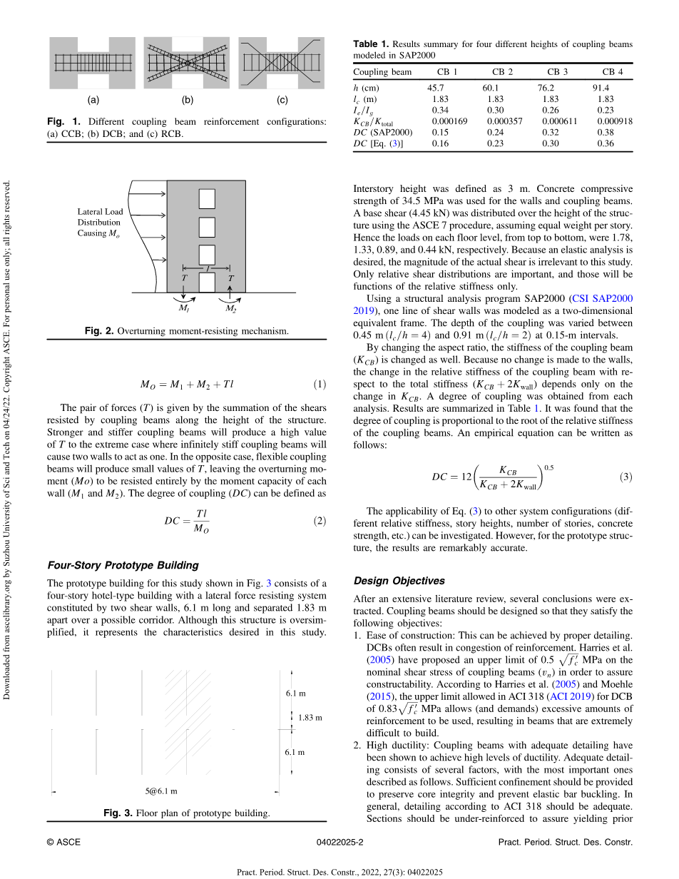
Lateral Load
Distribution
Causing M
T T
M1 M2
Rhombic Reinforced Coupling Beams
Rhombic reinforced coupling beams (RCBs) [Fig. 1(c)] are also known as truss reinforced coupling beams. This reinforcement configuration is relatively new but has already been used in tall structures such as the Satrio Tower in Indonesia (Tanuwidjaja 2007).Research (Tegos and Penelis 1988; Galano and Vignoli 2000;Harries and McNeice 2006; Park and Paulay 1975; Afefy 2020)has shown that RCBs exhibit superior behavior over both CCBs and DCBs. Additionally, RCBs are far easier to construct than
DCBs as they require no confinement reinforcement (Galano and Vignoli 2000). Unfortunately, there is not enough available research to incorporate the design of RCBs completely in this study.
Others
Coupling beams are also built using wide flange steel sections as beams or smaller steel sections as diagonal elements later embedded in concrete. These hybrid coupling beams are outside the scope of this research.
Degree of Coupling
The pair of forces (T) is given by the summation of the shears resisted by coupling beams along the height of the structure.Stronger and stiffer coupling beams will produce a high value of T to the extreme case where infinitely stiff coupling beams will cause two walls to act as one. In the opposite case, flexible coupling beams will produce small values of T, leaving the overturning moment (Mo) to be resisted entirely by the moment capacity of each wall (M and M ). The degree of coupling (DC) can be defined as.
Four-Story Prototype Building
The prototype building for this study shown in Fig. 3 consists of a four-story hotel-type building with a lateral force resisting system constituted by two shear walls, 6.1 m long and separated 1.83 m
apart over a possible corridor. Although this structure is oversimplified, it represents the characteristics desired in this study.
Interstory height was defined as 3 m. Concrete compressive strength of 34.5 MPa was used for the walls and coupling beams.A base shear (4.45 kN) was distributed over the height of the structure using the ASCE 7 procedure, assuming equal weight per story.Hence the loads on each floor level, from top to bottom, were 1.78,1.33, 0.89, and 0.44 kN, respectively. Because an elastic analysis is desired, the magnitude of the actual shear is irrelevant to this study.Only relative shear distributions are important, and those will be functions of the relative stiff
剩余内容已隐藏,支付完成后下载完整资料
资料编号:[588700],资料为PDF文档或Word文档,PDF文档可免费转换为Word
您可能感兴趣的文章
- 饮用水微生物群:一个全面的时空研究,以监测巴黎供水系统的水质外文翻译资料
- 步进电机控制和摩擦模型对复杂机械系统精确定位的影响外文翻译资料
- 具有温湿度控制的开式阴极PEM燃料电池性能的提升外文翻译资料
- 警报定时系统对驾驶员行为的影响:调查驾驶员信任的差异以及根据警报定时对警报的响应外文翻译资料
- 门禁系统的零知识认证解决方案外文翻译资料
- 车辆废气及室外环境中悬浮微粒中有机磷的含量—-个案研究外文翻译资料
- ZigBee协议对城市风力涡轮机的无线监控: 支持应用软件和传感器模块外文翻译资料
- ZigBee系统在医疗保健中提供位置信息和传感器数据传输的方案外文翻译资料
- 基于PLC的模糊控制器在污水处理系统中的应用外文翻译资料
- 光伏并联最大功率点跟踪系统独立应用程序外文翻译资料